( full specifications are in the manual for the device )
1. Traditional ACS GRS is implemented on the basis of technological equipment,
which are controlled by microprocessor complexes according to a centralized or decentralized scheme.
The proposed decentralized software and technical means are integrated into the technological one
equipment and allow to assemble the GRS self-propelled guns in accordance with the technological scheme.
The following technological products are offered as separate functional links for the layout of the GRS ACS:
• a natural gas heater (for example, Methane-5) with a complex for regulating the supply of fuel gas to the POLUM'YA-04 heater;
• complex of control of reduction of GRS (GRS control);
• intelligent regulators;
• FLOUTEK-TM-D gas odorization complex;
• complex of automatic refueling with odorant;
• FLOUTEK-TM commercial gas accounting complex;
• crane control unit with an indication of the intermediate position of the crane;
• a complex of telesignaling and telecontrol of general station and auxiliary equipment.
2. SAU GRS based on software and technical means integrated into the technological equipment is intended for:
• provision of operative control and operation of technological units of the HRS: switching, cleaning
gas, prevention of hydrate formation (gas heating, introduction of methanol), reduction, gas accounting and odorization
gas and safety valve control;
• reception and processing of signals from auxiliary systems for monitoring the work of the technological
HRS equipment: power supply, lightning protection and protection against static electricity, fire detection
and fire extinguishing, gas alarm, security alarm, corrosion protection, heating
and ventilation, communication and telemechanics, selection of gas for own needs of the GRS;
• work in the mode of round-the-clock automatic functioning.
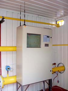
3. Technical means of self-propelled guns GRS, installed outside the explosive zone in
in the room of the operating room, are located in the control and control panel of the HRS. Technical means are explosion-proof
and can be installed in explosive zones, where the formation of explosive mixtures is possible.
4. Operation of the GRS ACS is allowed at an ambient air temperature of minus 40 to plus 60 °C.
5. SAU GRS is produced according to the technical conditions of TU U 73.1-31283392-008-2004.
1. SAU GRS provides:
• transformation and measurement of technological parameters in the controlled nodes of the HRS (temperature, pressure, pressure drop, flow rate, level);
• reception and transformation of discrete signals of the "dry contact" type, coming from the technological equipment and auxiliary systems of the GRS;
• control of the position of cranes and safety fittings;
• reception of control commands coming at the initiative of the GRS operator from the control panels of the reduction node and the switching node, installed on the front panel of the shield of the SHKU, or from the UMG control room (UMG DP);
• automatic and remote control of cranes and safety fittings;
• automatic and remote switching on/off of reduction lines;
• automatic disconnection of the GRS in the event of an accident;
• protection of consumers from inadmissible deviations of gas pressure at the outlet of the gas station by means of control
according to the given algorithm, taps or pressure regulators of reduction lines when the pressure deviates from
given limits;
• pressure regulation and/or volume flow limitation of gas at the output of the HRS reduction unit
by changing the task of the pressure regulators installed on the reduction lines;
• storage in the memory of the technical means of the ACS GRS of the values of the measured parameters and no less
8,000 messages about events that occur during the control and management of the technological equipment of the GRS,
and about the actions of the GRS operator and the UMG dispatcher when controlling the GRS ACS. At the same time, the date and time are fixed
(with discreteness of 1 s) formation of each message;
• indication on liquid crystal indicators (LCI) installed on control panels,
current and set limit values of the measured parameters, reasons for triggering the warning
and emergency signaling, as well as the reasons for the failure of the technical means of the GRS ACS;
• displaying on the monitor of the operator's built-in computer the mnemonic scheme of the HRS with
indication on it of current values of measured parameters, states of technological equipment, deviations from the norm
values of controlled technological parameters, indication of warning and emergency situations and their causes,
as well as the indication of diagnostic messages about the operation of complexes that are part of the GRS ACS;
• control of cranes, executive mechanisms, input and
adjustment of limit values of measured parameters, calling of diagnostic messages;
• calculation of gas consumption through the accounting node;
• accounting for the mass of the odorant introduced into the gas;
• accounting for the cost of consumed electricity;
• transfer at the request of the "upper level" of the data generated by the GRS ACS to the UMG SE;
• turning on sound and light signaling at the HRS and in the operator's house;
• transmission of voice messages to the GRS operator and UMG SE via GSM communication channel.
2. The upper limit of overpressure measurements is set according to the order in the range from 0.1 to 10.0 MPa.
3. SAU GRS provides temperature measurement in the range from minus 40 to plus 100 °C.
4. The limits of the reduced error, which is allowed, when measuring the excess gas pressure are:
±0.1; ±0.15 or ±0.25% of the upper limit of measurements.
5. The limits of the main absolute error allowed in temperature measurements are ±0.5 °С
or ±0.75 °С.
6. The GRS ACS has a standard RS232 or RS485 interface, which provides the possibility of connecting to a personal computer
for exchanging data and reading information.
7. SAU GRS provides power supply to the control solenoids of the cranes of each controlled reduction line and solenoids
safety armature control with direct current voltage (24+3) or (110+5) V.
8. Power supply of technical means of the GRS ACS:
• main - from an alternating current network with a voltage from 160 to 250 V and a frequency of (50±1) Hz;
• reserve - from a source of direct current power supply (accumulator battery) with
with a nominal voltage of 24 V. When the 220 V electrical network is disconnected, the SAU GRS continues to function fully
within 72 hours - preservation of measurement information and normal operation of all technical means of the GRS ACS is ensured.
9. The service life of the technical means of the GRS ACS is at least 12 years.
1. The control panel of the GRS ACS is located in the room (operator’s room)
outside the explosive zone and is mounted on a flat support.
2. The company provides 24-month warranty service for the technical means of the GRS ACS and service
throughout the service life.
![]() The documentation of SAU GRS is developed for each object separately.
The documentation of SAU GRS is developed for each object separately.

