
")


( full specifications are in the manual for the device )
1. Remote signaling device USD-2 is designed to receive and convert discrete signals
warning and emergency signaling coming from the control object (GDS), remembering the date and time of receipt
emergency signals and transmission of information about the signals in the coded package over the communication line to the
operator's home and/or to LPUMG control room with decoding of signals according to controlled parameters using LEDs installed on
front panel of both the transmitter and receiver of the device.
With the help of a GSM modem, it is possible to transfer information to the operator's mobile phone
in the form of voice or text messages.
2. The USD-2 device is not a measuring instrument.
3. Operation of the remote signaling device USD-2 is allowed at an ambient temperature of minus 40 to plus 60 °С.
1. The number of discrete inputs of the Device USD-2 - 8 pcs.
Discrete inputs of the transmitter are isolated (have galvanic isolation).
2. Type of input discrete signals - "dry contact" type or voltage from 12 to 24 V with input direct current up to 10 mA.
3. The number of discrete outputs of the transmitter and receiver of the USD-2 device (for the implementation of external
light and/or sound) signaling) - 2 each. The outputs provide switching of the DC electric circuit with voltage up to 12 V at
up to 5 A or up to 30 V at current up to 0.05 A and electrical circuit with voltage up to 220 V AC up to 0.5 A.
4. A dedicated two-wire line is used as a communication line between the transmitter and receiver.
The USD-2 device performs automatic control (diagnostics) of the state of the communication line (short circuit, break).
To ensure operational communication with maintenance personnel, mobile cellular communication is provided, which is implemented using
GSM modem and corresponding transmitter software.
5. The maximum distance between transmitter and receiver is 5000 m.
6. The device is powered by
DC power supplies:
- transmitter - from an external source with a voltage of 12 V;
- receiver - from an internal battery with a voltage of 6 V.
The transmitter has an internal 6V battery to save settings and keep the clock running.
The transmitter and receiver control the voltage of 6 V internal battery with an alarm when the battery is low.
7. Current consumed in standby mode, not more than:
-transmitter . . . . . . . - 0.2 A
- receiver . . . . . . . . . - 0.15 mA.
8. Overall dimensions of Remote signaling device USD-2:
- fastening on a DIN rail - dimensions of the receiver and transmitter - no more than 134 x 90 x 63 mm
- wall-mounted version - no more than 310 x 205 x 90 mm.
9. The service life of the remote signaling device USD-2 is at least 10 years.
1. The design of the remote signaling device USD-2 provides the possibility of placing them in the field
conditions and fasten in any working position on a flat support or - fastening on a DIN rail.
2. The company provides warranty service for devices within 24 months and after-sales service during the entire life time.
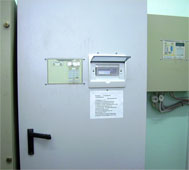 Fig. 1. An example of placement of the USD-2 Device in the control cabinet
![]() Remote signaling device USD-2.
Remote signaling device USD-2.