( full specifications are in the manual for the device )
1. The complex is designed to protect natural gas consumers from unacceptable deviations in gas pressure at the outlet
of the gas distribution station (GDS) by switching the reduction lines when the pressure deviates from the specified limits, as well as for regulation
pressure and gas flow limitation at the output of the reduction unit.
2. The complex is designed for round-the-clock automatic functioning as:
- autonomous protection device;
- a functional link in the control system of the technological equipment of the GRS.
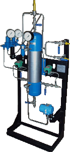
3. The complex consists of a pressure test set in an explosive zone on an organized site
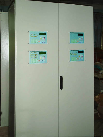
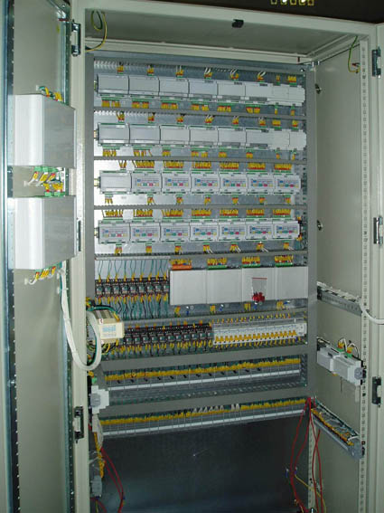
the gas reduction unit and the control panel of the reduction unit, installed outside the explosive zone (in the operator's room).
4. The complex is produced in series according to the technical conditions of TU U 73.1-31283392-007-2004.
1. The complex provides:
- measurement of excess gas pressure at the input and output of the reduction unit and at the output of the control unit task
pressure to pneumatic pressure regulators;
- control of the position of the cranes of each controlled reduction line;
- setting the status of each controlled reduction line (working, reserve disconnected or under repair);
- reception and transformation of information about the current volume flow of gas through the reduction node coming from the computer
volume consumption of gas;
- reception of control commands of the complex and reduction lines coming at the initiative of the GRS operator from the control panel
by the reduction node (hereinafter - the control panel) or from the UMG dispatch center (UMG Subdivision);
- automatic protection of consumers against inadmissible deviations of gas pressure at the outlet of the gas boiler by means of control according to the specified
the algorithm of the taps of the reduction lines when the pressure at the output of the HRS reduction node deviates from the specified limits;
- pressure regulation and/or limitation of gas volumetric flow rate at the outlet of the HRS reduction unit by changing (by the HRS operator,
by the UMG dispatcher) tasks to the pressure regulators installed on the reduction lines;
- storage in memory of a set of values of measured parameters and messages about events occurring in the technological
the process of gas reduction, and about the actions of the GRS operator and the UMG dispatcher when managing the complex;
- issuance of warning and emergency signaling signals to the HRS operator;
- indication on the liquid crystal display (LCD) of the control panel of the current and set limit values of the measured pressure,
the reasons for triggering the warning and emergency alarms, as well as the reasons for the malfunction of the complex;
- transfer on request of the "upper level" of the data generated by the complex, to the ACS of the GRS or to the SE of the UMG;
- turning on the sound and light alarm at the HRS and in the operator's house.
2. The maximum number of controlled and managed gas reduction lines . . . - 8.
3. Number of overpressure measurement channels . . . - 3.
The upper limit of measurements is set in the range . . . - from 100 to 10,000 kPa.
4. The limits of the reduced permissible error when measuring excessive gas pressure are ±0.10; ±0.15 or ±0.25%
the upper limit of measurements.
5. The complex provides electric power for the control solenoids of the taps of the reduction lines with a DC voltage of 24±3 or 110±5 V.
6. Power supply of the complex:
- main: - from an alternating current network with a voltage from 160 to 250 V and a frequency of (50+1) Hz.
- consumed power . . . . . . . . - 50 VA;
- reserve: - from a direct current power source (accumulator battery)
with a nominal voltage of 24 V.
- power consumption . . . . . . - 5 W.
When the 220 V electrical network is turned off, the complex continues to function fully for 24 hours.
At the same time, it ensures the preservation of measurement information and the normal operation of the complex with the possibility of up to 30 permutations of cranes,
with the consumption power of one faucet control solenoid up to 30 W.
7. The operation of the complex is allowed at an ambient air temperature of minus 40 to plus 60 °C.
8. The service life of the technical means of the complex is at least 10 years.
|
|
(pieces) |
1. Control panel of the reduction unit (includes:) |
1 |
- Controller MEGAS |
1 |
- Power control controller KUS-4 |
1 |
- mKUK crane management controller |
from 2 to 8 |
- The barrier is intrinsically safe BI-3 |
1 |
- The barrier is intrinsically safe BI-4 |
1 |
- Power supply JI 12/3 (with battery) |
1 |
- VPN converter 24/12 |
2 |
- VPN converter 110 |
1 |
2. Measuring pressure transducer PD-1-I |
2 |
3. ARBITR parallel access device |
|
4. Setting the pressure task (included:) |
1 |
- Receiver with control unit |
1 |
- Gas filter |
2 |
- Gas throttle |
2 |
- Safety valve |
1 |
- Electromagnetic valve with solenoid drive |
2 |
- Measuring pressure transducer PD-1-I |
1 |
1. The company provides warranty service for the complex within 24 months and service maintenance during the entire service life.
![]() The control system for the reduction of the power steering system of the GRS.
Operating instructions
The control system for the reduction of the power steering system of the GRS.
Operating instructions
![]() The control complex for the reduction of the power steering gear of the GRS.
The control complex for the reduction of the power steering gear of the GRS.


